Module description
To align face detection boxes with a preview, first restore detector outputs to the agreed original-image coordinates, then apply cropping, rotation, mirroring and preview scaling as required by the actual pipeline, including display offsets. This example uses crop, clockwise rotation, horizontal mirror and enlargement in that order; it is not a universal sequence for every device.
A shifted or reversed box does not necessarily indicate a detector fault. This page explains coordinate-module inputs, a mathematical example and verification methods; it does not announce a new SDK release.
Fields for the module interface
Swipe the table horizontally to view all columns.
| Object | Required fields | Purpose |
|---|---|---|
| Detection input | Original and detector-input sizes, preprocessing scale or padding | Restore model outputs to the agreed original-image coordinates |
| Crop and orientation | Original-image crop rectangle, rotation angle and direction, mirror position in the sequence | Define the transformation region and operation order |
| Preview region | Visible area, scaling mode, display offset and actual orientation | Distinguish fill-and-crop, complete-image display and padding |
| Output and traceability | Boxes, landmarks, timestamps, frame identifiers and transform configuration version | Associate results with the correct frame and configuration |
Expose the original boxes, five landmarks and preview overlay separately. If model preprocessing used padding or resizing, undo it before the agreed preview transform. Transform all box corners rather than only the center.
A hand-checkable orientation example
This is a mathematical example, not a device measurement. Use continuous-edge coordinates with the origin at the upper left, x to the right and y down. Crop a 640×480 image from (80,40) with size 320×240. Original point (120,70) becomes (40,30) after subtracting the coordinate origin of the cropped image. Rotate 90 degrees clockwise: (240−30,40)=(210,40), with new size 240×320. Mirror horizontally: (240−210,40)=(30,40). Scale by 2 with no added offset: the display point is (60,80) in a 480×640 region.
A · Original image
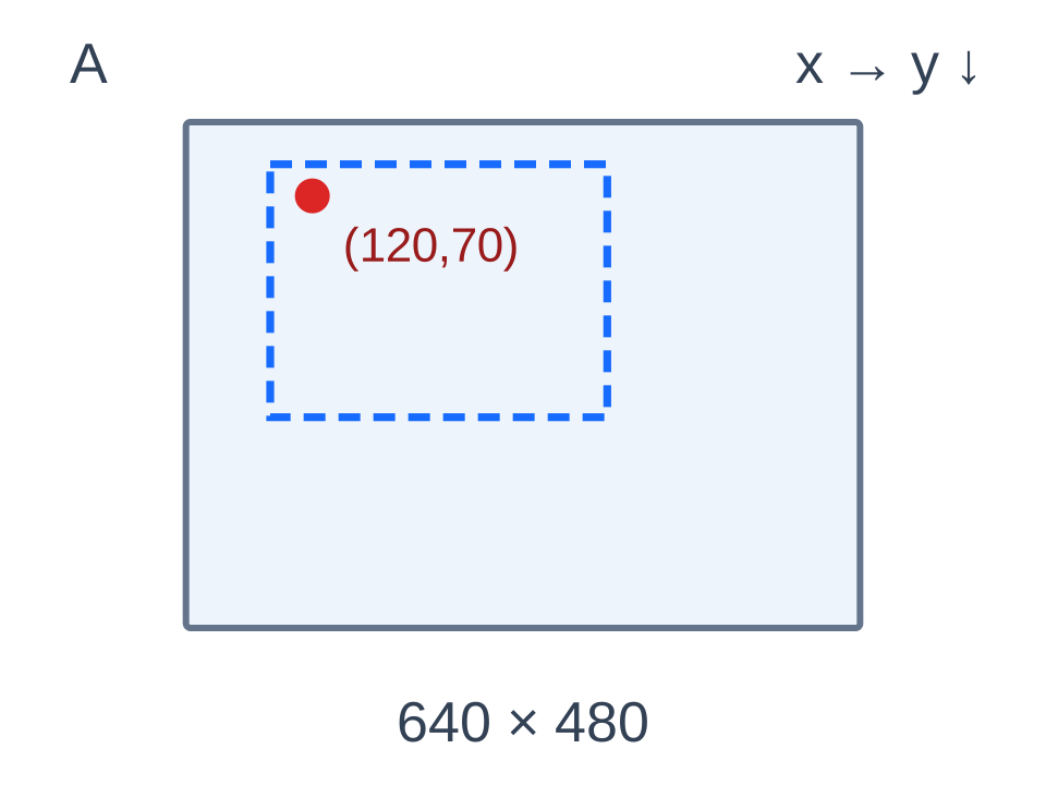
640×480 · (120,70)
B · After cropping
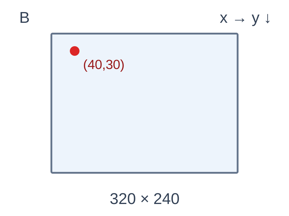
320×240 · (40,30)
C · Clockwise rotation by 90°
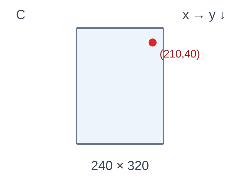
240×320 · (210,40)
D · After horizontal mirror
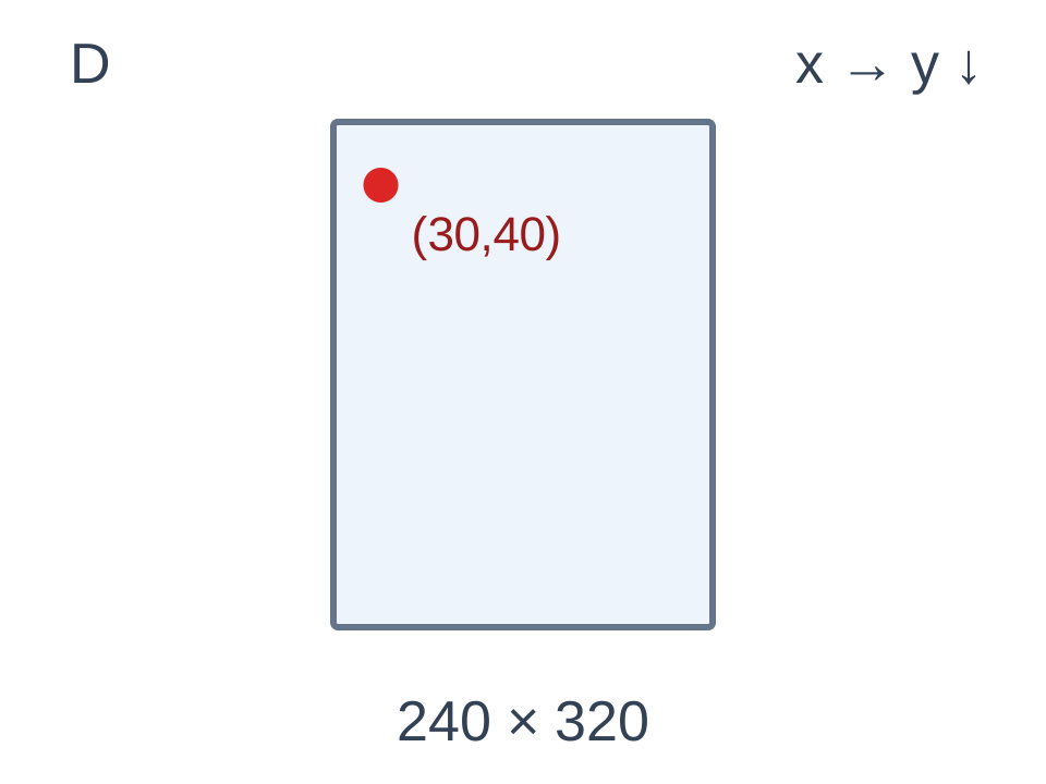
240×320 · (30,40)
E · After scaling by 2
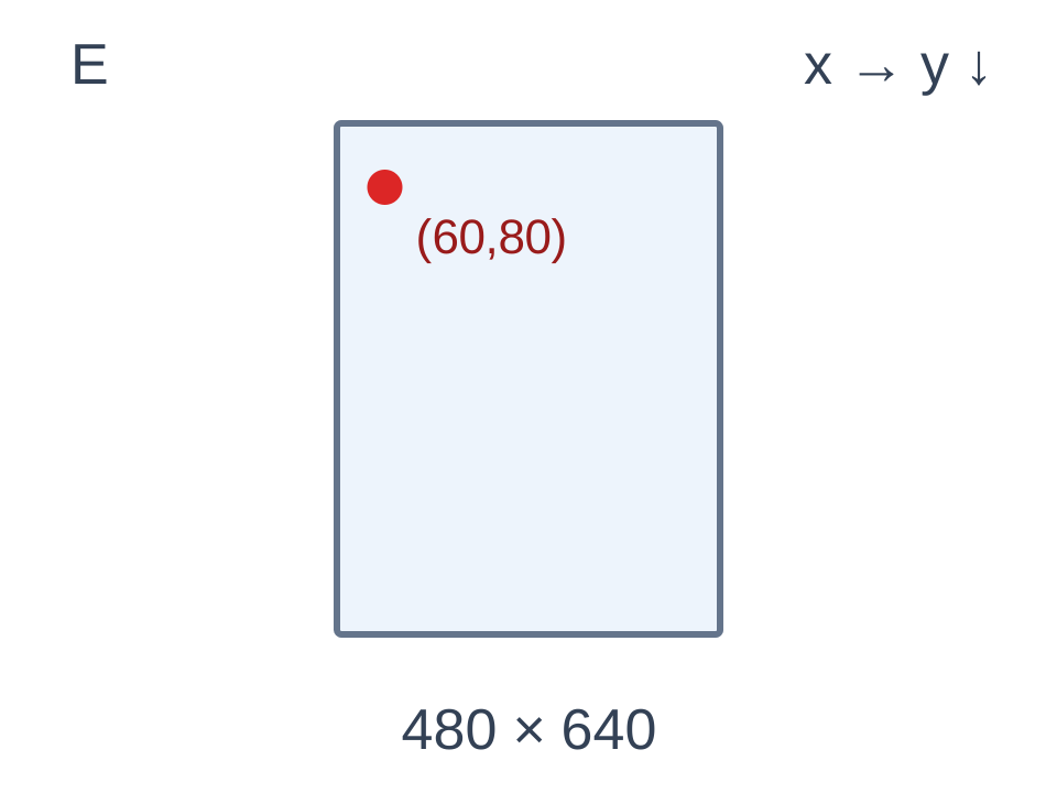
480×640 · (60,80)
The red point represents the same mathematical point. Each panel is drawn to its own image proportions; the displayed panel sizes cannot be compared as pixel dimensions. These are continuous-edge coordinate diagrams, not device detection results.
These are continuous-edge coordinates, so rotation uses height minus y. Discrete pixel-index code instead involves height minus 1 minus y; the conventions cannot be mixed directly. Consult the official Android Matrix documentation and check matrix composition against the actual input/output contract.
Separating geometric checks from device verification
Check corners, the center, asymmetric points and rectangles crossing image-cropping boundaries to verify order, bounds and inverse transforms. Transform all four rectangle corners and recompute the enclosing box. After geometric checks, verify sensor orientation, front/rear camera mirroring, preview scaling and screen rotation on the target device. Geometry checks do not establish live-pipeline behavior or long-term stability.
The Chinese-language RK3588 offline vision SDK project report provides face detection rectangles, landmarks and orientation. The public baseline uses YuNet CPU detection. It does not include identity recognition or measured NPU performance. Provide orientation-marked images, device information and preview layouts through the Chinese-language RK3588 Android adaptation service to define coordinate interfaces and target-device integration.

 Online

 Phone
Phone

 WeChat



 Top
Top