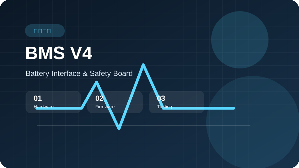
Project Background
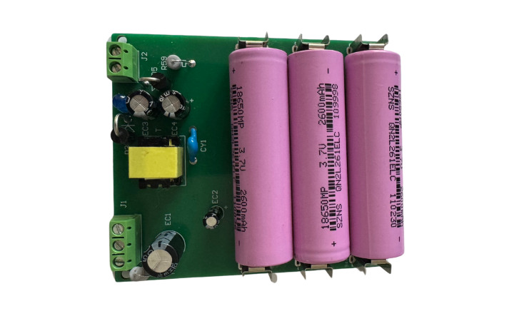
This project was built for the battery interface and safety protection needs of an underwater drone. The board sits between the main controller, battery BMS, leak detection, pressure sensing, CAN communication, and safety disconnect control. The goal was to integrate battery status acquisition, safety monitoring, fault reporting, and safety actions into a board that can be debugged, verified, and delivered.
Applicable Scenarios
This case is suitable for underwater robots, underwater drones, mobile robots, new energy equipment, and industrial devices that require battery interface boards, safety boards, sensor acquisition boards, or communication conversion boards.
Client Requirements
- Design 24V input power, low-voltage onboard power, MCU core, and pin allocation.
- Implement debug UART, BMS UART communication, CAN communication, and business frame reporting.
- Connect ADS1115 leak detection, MS8607 pressure sensor, ON/OFF reed switch input, and Opto_NO safety contact.
- Support pressure fault judgment, Flash latch, reset retention, lab clear command, and LED indicators.
- Prepare flashing procedures, test records, troubleshooting notes, and delivery documents.
Technical Solution
The project combined hardware design and embedded software development. The team first clarified the board position in the whole system, then divided the work into communication, sampling, safety control, and testability modules.
- Designed the BMS V4 hardware plan, power chain, MCU core, UART, CAN, ADS1115, MS8607, Opto_NO, reed switch input, and LED indication circuits.
- Built a USART2 9600 8N1 BMS communication framework with query, receive, and protocol parsing skeleton.
- Implemented CAN 1000 kbit/s base communication, 0x200+X, 0x300+X, 0x400+X reporting framework, and 0x12C software emergency stop logic.
- Implemented leak acquisition, leak/open-line identification, pressure acquisition, pressure fault judgment, Flash latch, and reset retention.
- Kept USART1 debug commands, PC-simulated BMS response frames, PCAN verification, and flashing troubleshooting procedures.
Core Functions
- BMS UART communication, PC-simulated BMS frames, and interfaces for later real battery joint debugging.
- CAN business frame reporting, dual-board address management, and frame distinction.
- ADS1115 leak acquisition, resistor-based leak simulation, and real water-bridge leak tests.
- MS8607 pressure acquisition and pressure fault judgment over 120 kPa for more than one second.
- Opto_NO safety control, ON/OFF reed switch input, ERROR LED, and SOC LED indication.
Implementation Process
The implementation started with hardware planning, schematic design, and interface definitions. The STM32 project then verified UART, CAN, sensor acquisition, and safety control logic one by one. Testing used PC-simulated BMS frames, PCAN tools, leak simulation resistors, water-bridge tests, and pressure-condition tests.
Testing and Verification
- Verified USART1 debug port, USART2 BMS UART 9600 8N1, and PC-simulated BMS response frames.
- Verified PCAN CAN transmission, 0x12C emergency stop logic, and business frame reporting.
- Verified ADS1115 sampling, 5.1k resistor leak simulation, and real water-bridge leak testing.
- Verified MS8607 pressure acquisition, pressure fault judgment, Flash write, and reset latch.
- Verified ST-LINK and Keil flashing procedures on the new board.
Delivery Results
- BMS V4 hardware design plan, interface definition, schematic, and PCB-related materials.
- STM32 Keil/CubeMX project, application source code, R3 firmware, and flashing output.
- Debug commands, test scripts, logs, troubleshooting records, and progress reports.
- Source delivery package, function summary, and follow-up joint debugging list.
Project Value
The project completed a staged loop from hardware design to embedded function verification for an underwater drone BMS V4 interface board. The board is ready for single-board core function verification and follow-up real battery, CAN/DroneCAN, signal matrix, and system-level validation.
Reusable Experience
Battery interface and safety board projects should define the power chain, communication interfaces, sensor sampling, fault latch, and recovery strategy early. For underwater, robot, and new energy devices, lab simulation, real sensor conditions, and full-system load tests should be separated into stages.
Project Boundary
This case summarizes project responsibilities and delivery results. Real battery response frames, DroneCAN node flows, final CAN signal matrix, alarm bit definitions, and long-term stability tests need to be confirmed with customer devices and on-site conditions.
Related Services
FAQ
Can this case be reused for other underwater equipment?
Yes. Similar architecture can be reused when a project involves battery status acquisition, leak detection, pressure sensing, communication reporting, and safety control.
Can development start before the BMS protocol is finalized?
Yes. The framework, simulated response frames, and parsing skeleton can be prepared first, then mapped to real fields after the battery is available.
Why is Flash fault latch needed?
For underwater equipment, pressure and leak risks need to remain traceable after reset, so maintenance teams can review the fault before restoring operation.

 Online

 Phone
Phone

 WeChat


 Top
Top